"Going Back in Time for Some Vintage Howdunit"
EAST Knowledge was pleased to host Bill Howland for its sixth meeting. The title of this meeting was “Going Back in Time for Some Vintage Howdunit”. Bill talked to the group about the earliest uses of vacuum tubes and some of the history of their development. We had a great turnout, but we’ll still try to summarize the talk to the best of our ability for those who couldn’t make it.
Some Early History
Bill discussed the discovery of “thermionic emission” which is what makes a vacuum tube possible. “Thermionic emission” occurs when you heat a material to a point that electrons are given enough thermal energy to escape the surface of the material. This effect was independently discovered by multiple people in the late 19th century.
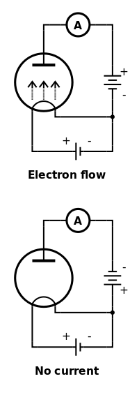
Thomas Edison rediscovered it while working on his light bulbs. In Edison’s case his rediscovery coincided with an observation he made while working on a particular configuration of his light bulb. His incandescent light bulb had a filament just like the ones you are probably familiar with, but he had inserted an additional foil element that was not connected to the filament in any way. While the filament was heated (the light bulb was on), Edison noticed that he could cause current to flow through the foil element in one direction, but not in the other.
This basic observation that current was only flowing one way through the foil was called the “Edison effect”. You'll notice in the diagrams above that current flows between the foil and the filament only when the battery on the right has the correct orientation.
Basic Construction of a Vacuum Diode
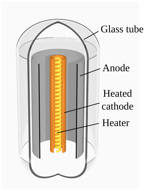
These days any circuit element that only allows current to flow one way is called a diode. The vacuum tubes that Bill discussed in his talk were diodes. Similar to Edison’s experimental bulb, a vacuum tube diode contains a heated element (cathode) and a cold element (anode). The heated cathode and cold anode are separated by a vacuum. When the cathode is heated, the gap between the anode and cathode will behave like a diode. Well, a much less than ideal diode, but a diode nonetheless.
Uses
Bill explained that one of the primary uses of a diode is for radio “detection”. A detector is often used to convert an AC (radio frequency) signal to a DC (baseband) signal. These diodes would have been used in radio receivers to detect signals from spark-gap, continuous wave (morse code), and AM transmitters. Another use for diodes is rectification. Power rectifiers are used to convert AC power into DC power as part of power supply circuits.
Other Interesting Tidbits
Vacuum tubes may have been electrical components, but Bill also described their interesting physical and mechanical construction. Since the operation of the vacuum tube relies on the absence of gas, an oxidizing metal is included inside the tube to help capture stray atoms of gas that may be lingering after the tube is evacuated. This oxidizing metal is referred to as a “getter” and is often seen as a metallic deposit on the surface of the glass.
Additionally, the mechanical separation of the filaments and anode and cathodes is critical to the operation of the vacuum tube. To keep the vacuum tube’s structure intact and rigid, mica spacers are often used. You’ll see those spacers at the top of the tubes in some of the photos.
Bill also mentioned how some of the higher voltage tubes that were used (e.g. in color TVs) would generate X-rays while in operation. These portions of the circuit would have been covered in a shielded box (thankfully) when in operation.
Reliability and Failure Modes
Bill noted that for low power, less complex gear like consumer radios, vacuum tubes are relatively reliable. You might need to replace a tube every three to five years. This seems to be on par with today’s consumer electronics with the advantage that you are able to repair the item instead of throwing it away once it breaks, as is typically done today.
However, due to the high voltages involved, vacuum tubes can have some spectacular failure modes. Here’s a picture of a tube that Bill brought that showed how the metal plate of the anode had been eaten away by arcing that had developed in the tube. Also noticeable is how the glass had deformed due to overheating.
Demos
After the main talk, Bill proceeded to his demonstrations. He had brought a power supply that he combined with some simple circuits so that he could demonstrate the differences in voltage drop for the various tubes that he had in his collection. Differences in voltage drop are an indication of efficiency of the tubes, with lower voltage drops indicating more efficient operation.
Sometimes Technology Needs to Scale Up
Bill provided many examples of various types of tubes. After the talk and demonstrations, people were looking over the tubes. Bill pointed out that while tubes did continue to get smaller over time, their performance characteristics remained about the same. Additionally, unlike semiconductor transistors, vacuum tubes rate of shrinkage was very low. You don’t find the high rate of size reduction that has allowed semiconductor integrated circuits to double their transistor count every 18 months or so.
At that point, somebody asked about modern applications of tubes. Bill mentioned audio amplifiers and Pat mentioned RF amplifiers used for broadcasting. Vacuum tubes are the technology of choice when you need high power combined with high bandwidth. Bill emphasized that vacuum tube technology can be readily scaled up for certain applications, which is an interesting contrast to semiconductor technology. Even in today’s world so focused on miniaturizing everything, sometimes it’s still important to be able to scale technology up and not just down.
That’s All for Now
It was a great talk, and we had a great time. We’d all like to thank Bill for taking the time and effort to present to the group. Bill has said that he is willing to come back and talk about other types of vacuum tubes and their applications. We intend to hold him to that offer!
Thank you to Gresham’s Multnomah County Library for hosting us, and thank you to everybody who made it out! We hope to see you next time!
References and Resources
Bill didn’t get a chance to talk about “PSU Designer”, which is a program hobbyists use to simulate and verify their tube power supply designs. You can find that program here: http://www.duncanamps.com/psud2/index.html.
Links to other resources:
- Wikipedia entry on thermionic emission: https://en.wikipedia.org/wiki/Thermionic_emission
- Wikipedia entry on rectifiers: https://en.wikipedia.org/wiki/Rectifier
- Wikipedia entry on vacuum tubes: https://en.wikipedia.org/wiki/Vacuum_tube
- Example of high power vacuum tubes: https://en.wikipedia.org/wiki/8974
- Bill’s website, “Evil Science Audio”: https://evilscienceaudio.wordpress.com/
- Wikipedia images:
- Edison Effect: https://commons.wikimedia.org/wiki/File:EdisonEffect.svg
- Vacuum Tube Diagram: https://commons.wikimedia.org/wiki/File:Diode-english-text.svg


