Sunday, November 29, 2015

Coffee Break #5 - Recap

I apologize for the tardiness of the recap, but the Thanksgiving holiday got the better of me. Speaking of holidays, EAST Knowledge will be taking a break during December. We'll pick up again at the start of 2016. We'll announce more once we firm up plans. As usual, if you have a topic you'd like to share with the group, please don't hesitate to say so. We're a very welcoming and enthusiastic group!

We had a nice turn out for our fifth Coffee Break at the pleasant Cafe Delirium. Pat brought his most recent incarnation of the head for his pick and place machine. You can see it below, but the camera on my phone does not do it justice. (Sorry, Pat!) We talked about a variety of things and enjoyed just chatting and catching up with each other. It was a good break!

Thank you, everyone, who came out for the coffee break! We hope to see you at our next event! Have a happy new year!

Sunday, November 8, 2015

Coffee Break #5

Update: A meeting recap.

We had a great meeting last month. For this month, we invite you to join us for coffee at Cafe Delirium. If you haven't made it to one of our talks, the coffee breaks provide a nice opportunity to drop by and introduce yourself. We have the room in the back reserved. We're going to hang out for a couple of hours, so feel free to come by, talk shop, show off what you're working on, ask questions and pick each other's brains. We look forward to seeing you there! All are welcome!

What:Coffee Break
Where:Cafe Delirium
308 N Main Ave, Gresham (map)
When:10:00am - Noon, Saturday, Novemeber 21st, 2015
Why:Sharing what we know over good coffee

Saturday, October 31, 2015

Recap "Going Back in Time for Some Vintage Howdunit" (Meeting #6)

"Going Back in Time for Some Vintage Howdunit"

EAST Knowledge was pleased to host Bill Howland for its sixth meeting. The title of this meeting was “Going Back in Time for Some Vintage Howdunit”. Bill talked to the group about the earliest uses of vacuum tubes and some of the history of their development. We had a great turnout, but we’ll still try to summarize the talk to the best of our ability for those who couldn’t make it.

Some Early History

Bill discussed the discovery of “thermionic emission” which is what makes a vacuum tube possible. “Thermionic emission” occurs when you heat a material to a point that electrons are given enough thermal energy to escape the surface of the material. This effect was independently discovered by multiple people in the late 19th century.

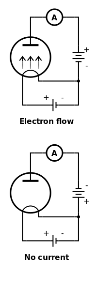
Thomas Edison rediscovered it while working on his light bulbs. In Edison’s case his rediscovery coincided with an observation he made while working on a particular configuration of his light bulb. His incandescent light bulb had a filament just like the ones you are probably familiar with, but he had inserted an additional foil element that was not connected to the filament in any way. While the filament was heated (the light bulb was on), Edison noticed that he could cause current to flow through the foil element in one direction, but not in the other.

This basic observation that current was only flowing one way through the foil was called the “Edison effect”. You'll notice in the diagrams above that current flows between the foil and the filament only when the battery on the right has the correct orientation.

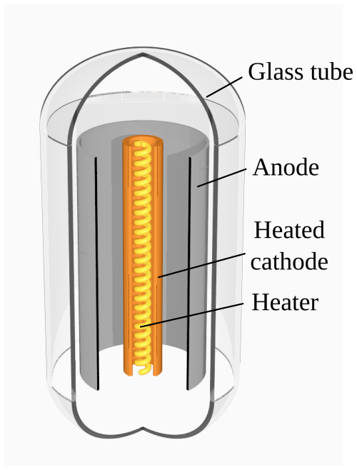
Basic Construction of a Vacuum Diode

These days any circuit element that only allows current to flow one way is called a diode. The vacuum tubes that Bill discussed in his talk were diodes. Similar to Edison’s experimental bulb, a vacuum tube diode contains a heated element (cathode) and a cold element (anode). The heated cathode and cold anode are separated by a vacuum. When the cathode is heated, the gap between the anode and cathode will behave like a diode. Well, a much less than ideal diode, but a diode nonetheless.

Uses

Bill explained that one of the primary uses of a diode is for radio “detection”. A detector is often used to convert an AC (radio frequency) signal to a DC (baseband) signal. These diodes would have been used in radio receivers to detect signals from spark-gap, continuous wave (morse code), and AM transmitters. Another use for diodes is rectification. Power rectifiers are used to convert AC power into DC power as part of power supply circuits.

Other Interesting Tidbits

Vacuum tubes may have been electrical components, but Bill also described their interesting physical and mechanical construction. Since the operation of the vacuum tube relies on the absence of gas, an oxidizing metal is included inside the tube to help capture stray atoms of gas that may be lingering after the tube is evacuated. This oxidizing metal is referred to as a “getter” and is often seen as a metallic deposit on the surface of the glass.

Additionally, the mechanical separation of the filaments and anode and cathodes is critical to the operation of the vacuum tube. To keep the vacuum tube’s structure intact and rigid, mica spacers are often used. You’ll see those spacers at the top of the tubes in some of the photos.

Bill also mentioned how some of the higher voltage tubes that were used (e.g. in color TVs) would generate X-rays while in operation. These portions of the circuit would have been covered in a shielded box (thankfully) when in operation.

Reliability and Failure Modes

Bill noted that for low power, less complex gear like consumer radios, vacuum tubes are relatively reliable. You might need to replace a tube every three to five years. This seems to be on par with today’s consumer electronics with the advantage that you are able to repair the item instead of throwing it away once it breaks, as is typically done today.

However, due to the high voltages involved, vacuum tubes can have some spectacular failure modes. Here’s a picture of a tube that Bill brought that showed how the metal plate of the anode had been eaten away by arcing that had developed in the tube. Also noticeable is how the glass had deformed due to overheating.

Demos

After the main talk, Bill proceeded to his demonstrations. He had brought a power supply that he combined with some simple circuits so that he could demonstrate the differences in voltage drop for the various tubes that he had in his collection. Differences in voltage drop are an indication of efficiency of the tubes, with lower voltage drops indicating more efficient operation.

Sometimes Technology Needs to Scale Up

Bill provided many examples of various types of tubes. After the talk and demonstrations, people were looking over the tubes. Bill pointed out that while tubes did continue to get smaller over time, their performance characteristics remained about the same. Additionally, unlike semiconductor transistors, vacuum tubes rate of shrinkage was very low. You don’t find the high rate of size reduction that has allowed semiconductor integrated circuits to double their transistor count every 18 months or so.

At that point, somebody asked about modern applications of tubes. Bill mentioned audio amplifiers and Pat mentioned RF amplifiers used for broadcasting. Vacuum tubes are the technology of choice when you need high power combined with high bandwidth. Bill emphasized that vacuum tube technology can be readily scaled up for certain applications, which is an interesting contrast to semiconductor technology. Even in today’s world so focused on miniaturizing everything, sometimes it’s still important to be able to scale technology up and not just down.

That’s All for Now

It was a great talk, and we had a great time. We’d all like to thank Bill for taking the time and effort to present to the group. Bill has said that he is willing to come back and talk about other types of vacuum tubes and their applications. We intend to hold him to that offer!

Thank you to Gresham’s Multnomah County Library for hosting us, and thank you to everybody who made it out! We hope to see you next time!

References and Resources

Bill didn’t get a chance to talk about “PSU Designer”, which is a program hobbyists use to simulate and verify their tube power supply designs. You can find that program here: http://www.duncanamps.com/psud2/index.html.

Links to other resources:

  1. Wikipedia entry on thermionic emission: https://en.wikipedia.org/wiki/Thermionic_emission
  2. Wikipedia entry on rectifiers: https://en.wikipedia.org/wiki/Rectifier
  3. Wikipedia entry on vacuum tubes: https://en.wikipedia.org/wiki/Vacuum_tube
  4. Example of high power vacuum tubes: https://en.wikipedia.org/wiki/8974
  5. Bill’s website, “Evil Science Audio”: https://evilscienceaudio.wordpress.com/
  6. Wikipedia images:
    1. Edison Effect: https://commons.wikimedia.org/wiki/File:EdisonEffect.svg
    2. Vacuum Tube Diagram: https://commons.wikimedia.org/wiki/File:Diode-english-text.svg
Sunday, October 11, 2015

Going Back in Time for Some Vintage Howdunit (Meeting #6 Announcement)

Update: A meeting recap.

EAST Knowledge is excited to announce it's sixth meeting. Bill Howland will re-introduce us to vacuum tubes and their uses. Come and learn something old!

What:Going Back in Time for Some Vintage Howdunit
Who:Bill Howland
Where:The Meeting Room at the Gresham Library
385 NW Miller Ave, Gresham (map)
When:10:30am - Noon, Saturday, October 24th, 2015
Why:Sharing what we know

Bill Howland will:

  • Give a summary of the origins of vacuum and gas diodes and related thermionic devices
  • Have show-n-tell demonstrations of the earliest and simplest of such devices: The diode

Vacuum tube diodes were put to use in the early days of radio as "detectors", because they were more robust and reliable than crystal, mechanical, and chemical contrivances used for this purpose. With further development, thermionic vacuum and gas diodes advanced to be capable of power rectification with ever greater efficiencies.

Many example devices from the 1930's to 1950's will be available to examine. There will be orange, purple, and blue glows in the demonstrations!

Come and share what you know or just come to learn what other people know! All are welcome!

Bill shares some of his projects on his blog: Evil Science Audio

Saturday, September 5, 2015

Coffee Break #4

After taking a break over summer, EAST Knowledge is ramping up again with a coffee break. We invite you to join us for coffee at Cafe Delirium. If you haven't made it to one of our talks, the coffee breaks provide a nice opportunity to drop by and introduce yourself. We have the room in the back reserved. We're going to hang out for a couple of hours, so feel free to come by, talk shop, show off what you're working on, ask questions and pick each other's brains. We look forward to seeing you there! All are welcome!

What:Coffee Break
Where:Cafe Delirium
308 N Main Ave, Gresham (map)
When:10:00am - Noon, Saturday, September 19th, 2015
Why:Sharing what we know over good coffee

Sunday, May 17, 2015

Coffee Break #3 - Recap

We held our third Coffee Break at the pleasant Cafe Delirium. We had enough people show up that we may have to consider a location that can accommodate more people for next time. We forgot to take pictures again, but I did try to do a better job of taking notes.

  • Pat brought his Arietta board to show us. He had attached a proximity detector on to the I2C bus. The proximity detector has a range of 5mm - 100mm. He is investigating incorporating the detector into his pick and place machine (previously discussed here and here).
  • Pat also mentioned a youtube video which gave what he felt was an elegant explanation for capacitors in series. (I'm still tracking down that video, so I'll try to update this page when I get a link.)
  • We briefly discussed the pros and cons between Xilinx and Altera FPGA development tools and their different soft CPU cores.
  • We also talked about a desire to learn more about Linux containers and web development frameworks. Charles is using some of these things in his work, and utilized containers in the IPython notebook demo he gave to the group.
  • Michael thought to bring with him several examples of items he had printed from his 3D printer. He has been finding many uses for it.
    • He discussed some of the pros and cons of the designs that can be found on Thingiverse.
    • He prefers to use Thingiverse for inspiration for creating his own designs as he has found he often cannot use the designs straight from the site.
    • He mentioned that he has discovered the importance of the interaction of the slicer software and the printer control software, and he has learned a lot about the work flow for 3D printing.
    • Michael pointed out that the company that produces his printer has just announced a smaller scale printer: Printrbot Play.
  • We also discussed vacuum tube audio amplifiers and restoring other older equipment. Bill has found he can often find many pieces of older test equipment that can be had cheaply and just needs a little effort to get working again.
    • As we were discussing this, Chuck mentioned that at one time people actually installed phonographs into their cars. Something that most of us did not realize, and we were astounded that people would actually play their records while driving down the road. Virginia later dug up some internet evidence of these entertainment systems.

That's everything from my notes, and I know these are just the highlights. If I've left anything out you'd like me to include, please don't hesitate to mention it.

I think everybody had a good time. The coffee breaks make a great opportunity for pleasant, wide ranging conversations. Thank you to everybody who came out. And if you couldn't make it, we hope to see you next time!

Tuesday, May 5, 2015

Coffee Break #3

Update: A meeting recap.

EAST Knowledge is pleased to announce it's third "Coffee Break"!

We invite you to join us for coffee at Cafe Delirium. If you haven't made it to one of our talks, the coffee breaks provide a nice opportunity to drop by and introduce yourself. We have the room in the back reserved. We're going to hang out for a couple of hours, so feel free to come by, talk shop, show off what you're working on, ask questions and pick each other's brains. We look forward to seeing you there! All are welcome!

What:Coffee Break
Where:Cafe Delirium
308 N Main Ave, Gresham (map)
When:10:00am - Noon, Saturday, May 16th, 2015
Why:Coffee and sharing what we know

Tuesday, April 21, 2015

Meeting #5 - Recap

"Locating Intrusions Using Fiber Optics"

For its fifth meeting, EAST Knowledge was pleased to have Jim Rulla as its guest speaker. Jim previously spoke at EAST Knowledge for our second meeting, and he was gracious enough to come back. The topic of this meeting was “Locating Intrusions Using Fiber Optics”. As usual, we’ll do our best to report on the talk, but these summaries are in no way intended as a substitute to seeing the talks in person.

Jim, always an engaging speaker, opened his talk by showing the audience a front page news story from 2012 about a man whose jet ski had broken down while riding it New York's Jamaica Bay. The man swam three miles to shore and climbed the fence at the JFK airport without detection. It was a dramatic example of the importance of perimeter security, and an example of where the technology Jim was about to talk about could be applied.

Basics of Interferometry

Jim gave a basic description of interferometry. Interferometry is a way to perform high precision measurements on the order of wavelengths of light. Interferometry relies on the wave properties of light. When multiple waves are combined, they add together. This adding together can be constructive (when both waves are positive), or destructive (when one wave is positive and the other negative). A basic interferometer uses a laser source, a beam splitter, two mirrors, and a detector. Example from wikipedia:

The key to the interferometer shown above is that the light travels along two different paths but are recombined in the detector. Now if you move one or both mirrors, the path length of the two light beams will change. This will cause fringes to appear at the detector as the two light beams will be slightly out of phase with one another. If you are varying the position of the mirrors in time, the fringe patterns will also vary in time. Example fringe patterns:

How Interferometry can be Used to Detect Intrusion

Jim had his custom software that he used to demonstrate the basic sort of signals that would be generated by a an interferometer. In the picture you see below, there are two large plots. The large plot on the bottom represents the position of one of the mirrors over time. The large plot on the top represents the signal that is detected where the two light beams come back together. As the mirror moves up and down (changing the path length the light travels), you can see the affect on the brightness of the light. Notice that when the mirror isn’t moving, the signal is flat (left side of plots).

Top plot represents interferometer signal. Bottom plot is the mirror position. Notice that when the mirror isn’t moving, the signal is flat (left side of plots).

To detect an intrusion using interferometry, you would need an interferometer where an intrusion would disturb the path length of light. You can create an interferometer using fiber optics. If you then run the fiber optics along a fence (for example), any disturbance on the fence will cause a disturbance in the fiber optics. This in turn changes the path length of the light, which will create interference patterns that are then detected. In the absence of an intrusion, you have a flat signal. Once an intrusion occurs, the signal begins to change rapidly. Detecting when the signal is changing is all that is needed to detect the intrusion.

Jim also mentioned that basic interferometry makes it difficult to determine which direction the path length has changed. You’ll notice in the plot shown above that as the mirror changes direction, the output of the basic interferometer continues to change in the same way. However, modulating the light being used from the interferometer provides phase information. One possible way of doing that is by vibrating one of the mirrors. This technique is known as "homodyne modulation".

How Interferometry can be Used to Detect Location

Now that we have a basic interferometer detection, how can that be used to detect location? Jim showed a diagram (poorly) captured in the photo below. In the top, you see two fiber optic interferometers (one black the other red). These interferometers run in opposite directions in the same bundle of fiber. Because the interferometers are in the same bundle, what happens to one interferometer also happens to the other. If an intruder is climbing a fence, he will disturb both interferometers.

Because the interferometers are running in opposite directions, the signal produced by one interferometer is displaced in time relative to the other interferometer (see the red and black step plot in the picture below). This time difference varies depending on where the intrusion occurs. If you can calculate the time difference, then you can determine the location of the intrusion because you know the speed of light. Pretty cool!

In order to determine the time difference you have to perform a correlation on the two signals. The correlation isn’t perfect and can be computationally expensive, but using the correlation, you can get an estimate of the time difference between the intrusion signals.

The two interferometers running in opposite direction are shown on top. In the middle you see a simple plot showing the interferometer signals from a single intrusion. Notice that the intrusion signals are offset in time.

Jim showed that with this method of determining location that there is a direct relationship between the speed of light and how rapidly you would have to sample the signals. For example, to try to get an accuracy of +/- 25 m, you have to sample the interferometer at least 10 MHz. He further emphasized that if you have a typical DSP running at 500 MHz, that you would only get 50 clock cycles per sample. That means that to properly process the incoming data, you need to have the appropriate model and the appropriate, efficient approach. Using his software, Jim showed off several different approaches to processing the signals. In one example he emphasized the processing speed. In another he emphasized the accuracy and certainty of the location calculation. He suggest that for this particular application it is possible to get both.

Afterwards

Both during and after the talk, the audience had a lot of great questions and made several astute observations. We also have some leads on possible future talks. For anybody who might be interested in discussing some tech topics that interest them, get in touch. You’ll find a receptive audience with EAST Knowledge. If you’re eager to share, we’re eager to learn.

We hope to see you next time for stimulating conversation. (We also have coffee, cookies, and Raspberry Pi.)

References and Resources:
  1. Link to jet ski story: http://abcnews.go.com/US/jet-skier-broke-jfk-airports-security-wanted-caught/story?id=17550202
  2. More on interferometry: https://en.wikipedia.org/wiki/Interferometry
  3. More on homodyne modulation: http://en.wikipedia.org/wiki/Homodyne_detection
  4. More on correlation: https://en.wikipedia.org/wiki/Cross-correlation
  5. Patent on Intrusion Location: Apparatus and method for monitoring a structure using a counter-propagating signal method for locating events
  6. Jim's talk for meeting #2, announcement and recap:
    1. Announcement: http://www.eastknow.org/p/events.html#meeting-2
    2. Recap: http://www.eastknow.org/2014/03/meeting-2-recap.html
  7. Wikipedia images:
    1. Interferometer: https://commons.wikimedia.org/wiki/File:Interferometer.svg
    2. Fringes: https://commons.wikimedia.org/wiki/File:Colored_and_monochrome_fringes.png

Saturday, April 4, 2015

Meeting #5 Announcement - Locating Intrusions Using Fiber Optics

Update: A meeting recap.

EAST Knowledge is excited to announce it's fifth meeting. Jim Rulla will be giving a talk about how fiber optics can be used as sensors for locating intrusions. Come and learn something new! Come and share what you know! All are welcome!

What:Locating Intrusions Using Fiber Optics
Who:Jim Rulla
Where:The Story Room at the Gresham Library (map)
When:10:30am-Noon, Saturday, April 18th, 2015
Why:Sharing what we know

Interferometers measure distances to within fractions of the wavelength of light. Put a couple of these incredibly sensitive devices on the fence around an airport, and you can not merely detect a would-be intruder — you can locate him. Put a pair on a pipeline, and you can not merely detect nearby digging that could damage the pipe — you can locate its source. You might even be able to detect — and perhaps even locate — leaks in the pipe.

The detection and location mechanisms are fascinating examples of clever engineering. I'll explain how these patented systems work and illustrate new algorithms that improve performance.

Tuesday, March 31, 2015

Coffee Break #2 - Recap

We held our second Coffee Break at the pleasant Cafe Delirium. As usual, we had a friendly group show up. We forgot to take pictures this time, but that's only because we were engrossed in our conversations. I attempted to gather notes about what was discussed, but I admit that I didn't start taking notes until late into our conversations.

  • Discussed Jim Rulla's upcoming talk Locating Intrusions Using Fiber Optics. I hope to get an email announcement out in the next few days.
  • Discussed some of the differences and challenges between the industry in China and industry in the US.
    • Discused some of the strange economics that come into play. For instance being able to do three turns of a circuit board (assuming you have the time and right quantities) using manufacturers in China with less money than it would take to do a single turn in the US.
    • Andrew "bunnie" Huang's efforts to reverse engineer a SOC From Gongkai to Open Source. Choice quote: "I want to be able to use a 364 MHz 32-bit microcontroller with megabytes of integrated RAM and dozens of peripherals costing $3 in single quantities, instead of a 16 MHz 8-bit microcontroller with a few kilobytes of RAM and a smattering of peripherals costing $6 in single quantities."
  • Brought up how current chip manufacturing is handled by robots with the silicon wafers being placed and handled in large caddies (called FOUPs) where a single caddy of finished chips can represent several tens of millions of dollars. This reminded somebody of a video presentation that included a clip of an incident in a plant. (The whole video is worth watching.)
  • Discussed the use of Cython which Pat may try to incorporate into a future talk.
  • Pat brought up how you can combine Encfs with a Dropbox-like service to create an encrypted volume that is synchronized to the cloud without the cloud being able to see what is stored.
    • This is easily used under Linux with FUSE, but apparently there is an equivalent option under windows called Dokan.
  • We briefly discussed the potential to use a Raspberry Pi as a media center PC. It was also mentioned how easy it is to change the "personality" of a Raspberry Pi by swapping SD cards. This allows you to quickly repurpose a Raspberry Pi.
  • Some amount of discussion about how small technology companies can contribute meaningfully to local economic development. We stressed how small companies and individual consultants often service larger companies.

That's all I can remember for now. If there's anything you'd like me to include, please don't hesitate to mention it. Thank you to everybody who came out. And if you couldn't make it, we hope to see you next time at one of our regular meetings!

Sunday, March 8, 2015

Coffee Break #2

Update: A meeting recap.

EAST Knowledge is pleased to announce it's second "Coffee Break"!

EAST Knowledge is going to try a repeat of our first "Coffee Break". The first had a lot of great discussions. We invite you to join us for coffee at Cafe Delirium. We have the room in the back reserved. We're going to hang out for a couple of hours, so feel free to come by, talk shop, show off what you're working on, ask questions and pick each other's brains. We look forward to seeing you there! All are welcome!

What:Coffee Break
Where:Cafe Delirium
308 N Main Ave, Gresham (map)
When:10:00am-Noon, Saturday, March 28th, 2015
Why:Sharing what we know and what we're up to

Sunday, February 22, 2015

Meeting #4 - Recap

To celebrate a year of EAST Knowledge, Pat Nystrom returned for meeting #4 where he showed off two things:

  1. Recent work on his pick and place machine
  2. A DIY solder mask application

Pat is an engaging, knowledgeable speaker and he gave a tremendous talk. As usual, we’ll do our best to capture the meeting in these humble notes, but we won’t pretend to do the speaker justice. You really have to see these presentations in person.

Pick and Place Machine

When Pat last talked at EAST Knowledge he showed us his nearly completed pick and place machine. Pat’s goal is to produce a low cost pick and place machine for hobbyists and prototype assembly. He wants to combine what people do best with what machines do best. His pick and place machine will allow the human operator to pick up parts, while letting the machine perform final placement.

However, before finishing his machine, Pat was contacted to perform some other work that had extremely tight deadlines and required PCB assembly of multiple boards. The deadlines were so tight that he would not have been able to have the PCBs assembled by a manufacturing firm, so Pat turned to his mostly finished pick and place machine to assemble the boards himself. However, he found that while his current pick and place machine had buttery smooth motion when manually operated (as intended), it did not have the fine control he desired for part placement while being operated manually.

Manual Pick and Place

So Pat put together a new pick and place frame. For the two axes, this has rigid arms with small rollers that can be manipulated with the fingers for fine adjustment. Each axis has just enough stiction to keep from moving while the other axis is being adjusted. Additionally, Pat outfitted the parts head (taken from the previous machine) with a digital camera that he could use to see where the part was while placing it.

The machine isn’t perfect. For instance, the camera doesn’t have a perfect view of the part needle, so getting used to where the needle would place the part required a small learning curve. Despite the limitations, the machine allowed Pat to stuff 16 boards with small scale parts in about 4 hours without the fatigue and mistakes he would’ve experienced had he been using magnifiers and tweezers. Additionally, he successfully completed the prototypes. It’s hard to argue with success.

For the future, Pat would like to add a second camera to the head to provide a better view, and a laser dot that will provide an easy way to see where the part will be placed.

Lessons Learned

Beyond the technical issues, Pat felt he learned some valuable lessons while working on the manual pick and place. Being forced to work quickly required him to come up with ideas that he could try out quickly. This rapid pace allowed him to discover bad ideas earlier and discard them. Whereas before he was trying to get to product completion quickly, he is now thinking more along the lines of iterating his way to product refinement. Additionally, the manual pick and place is useful as it is right now even without all the automation. Focusing on having a useful product at each stage of development also allows for rapidly trying ideas.

It appears that the pick and place machine itself feeds into Pat’s entire process. It allows him to rapidly try ideas on not just the pick and place machine but also on the other things he works on.

DIY Solder Mask Application

After showing us his work on the pick and place machine, Pat gave a demonstration of a method he has developed for applying solder masks to his prototype circuit boards. Pat mills his own circuit boards, but the method will apply to any circuit boards you may make or have made. While you don’t need solder masks just for a prototype board, having a solder mask:

  • Improves the reliability of the board
  • Increases the lifetime of the board
  • Makes it easier to rework the boards

In short, it is often better to have a solder mask, so being able to apply a solder mask to boards you make yourself is a boon.

How it Works

Pat found a source of solder mask material that comes as a sheet. One side of the sheet is adhesive. This material is light sensitive, so Pat keeps it rolled up in a tube.

Required materials and tools:
  1. Solder mask material
  2. Solder mask stencil (it’s black everywhere you don’t want solder mask, i.e., over the component pads)
  3. Exposure frame
  4. Laminator (Pat used a Harbor Freight laminator)
  5. UV Light source (Pat used a lamp that is normally used to cure finger nail polish)
  6. Masking Tape
  7. Exacto blade
  8. Scissors
  9. Latex gloves (mostly for cleanliness)
  10. Canned air
Steps:
  1. Warm up the laminator.
  2. Wash PCB and dry with canned air.
  3. Cut a piece out of the sheet of solder mask material to be bigger than your PCB. Pat used scissors to get a rough cut.
  4. Using masking tape, attach to the dull side of the solder mask sheet, and pull off the protective covering. This exposes the adhesive side.
  5. Apply the adhesive side to the PCB.
  6. Use the exacto blade to trim off the excess material.
  7. Run the PCB through the laminator. This will cause the solder mask material to adhere to the PCB surface.
  8. Tape the stencil to the bottom of the exposure plate. Make sure the ink side of the stencil is away from the plate (which will be towards the PCB).
  9. Close the exposure plate down over the PCB and align the PCB to the stencil.
  10. Once the stencil and PCB are aligned. Clamp the exposure plate down so that the PCB won’t move.
  11. Place the PCB into the UV light source for about 2 minutes. Let cure for another 5 minutes (optional).
  12. Remove the PCB from the exposure frame, and lift the top protective sheet from the solder mask.
  13. Use sodium carbonate and a brush to remove uncured solder mask material. Anywhere the UV light was blocked by the stencil should come right off.
  14. Rinse the board again.
  15. Enjoy your freshly solder masked PCB!

Pat was talking to the group as he demonstrated his method, but it looks like it only takes a few minutes of work to apply the solder mask.

Exposure Frame:

Stencil:

The UV source being applied to circuit board in the exposure frame:

The circuit board with solder mask applied. The green areas are where the solder mask stuck, and the copper areas are just the bare circuit board:

This was another excellent demonstration of Pat’s methods for quickly bringing his circuit ideas to life.

Tuesday, January 27, 2015

Meeting #4 Announcement - The Evolution of Hardware Design in the Home Lab

Update: a meeting recap.

EAST Knowledge is pleased to announce it's fourth meeting. Pat Nystrom will be giving demonstrations on his efforts to make it easier to prototype electronics at home. All are welcome!

What:The Evolution of Hardware Design in the Home Lab
Who:Pat Nystrom
Where:The Computer Lab at the Gresham Library (map)
When:10:30am-Noon, Saturday, February 14th, 2015
Why:Sharing what we know

Pat Nystrom led off our EAST Knowledge series a little over a year ago, and we wanted to bring him back to see what he's been working on. He will be talking about and demonstrating two topics:
  • A dry-film soldermask process which makes home-made circuit boards much friendlier to use
  • An update on the development of his manual pick-place machine
Come and learn something new!

Solder masks are used in electronics manufacturing both to protect copper traces and to keep solder from going where it shouldn't.

Pick and place machines are devices used in electronics manufacturing. They come in various sizes, but they are commonly expensive. Pat is working on something that would be suitable and affordable for enthusiasts or prototype manufacturing.